

How to Install Metal Roof Flashing?
Installing metal roof flashing is not a decorative finishing step. It is the roof’s working barrier against driven rain, melting snow, wind, and repeated movement. Around chimneys, skylights, valleys, vents, and wall intersections, small installation errors can create serious leaks. Water may travel beneath panels before appearing indoors, making the original problem difficult to locate.
Metal roofing specialist Rob Haddock has emphasized, “A metal roof is a system, not a product.” That principle matters here. Metal roof flashing must work with the panels, underlayment, fasteners, sealants, and roof slope. One component cannot compensate for another. This guide explains how to install metal roof flashing with practical attention to layout, material compatibility, and water flow. It focuses on details that are easy to overlook, such as hemmed edges, expansion movement, exposed fastener placement, and the direction of overlapping joints.
Real roofs are rarely perfect. Existing walls may be uneven. Old sealant may hide damaged wood. A flashing cut can look clean but still direct water toward a seam. That is where careful inspection becomes more valuable than speed. Measure twice. Dry-fit each piece. Check the drainage path before fastening anything permanently.
Some instructions may feel conservative. They are. Manufacturer requirements can differ by panel profile and climate. When this guide and the product instructions disagree, the product instructions should control. A reliable installation also includes appropriate fall protection and professional review when roof conditions exceed your experience. The goal is simple: keep water moving outside, while allowing the roof system to expand, contract, and remain serviceable for years.
Choosing Materials and Planning the Flashing Layout
How to Install Metal Roof Flashing?
Choosing Materials and Planning the Flashing Layout
Metal roof flashing works best when its materials and layout are planned together. I usually begin with a roof sketch, marking valleys, wall intersections, vents, chimneys, eaves, and rakes. These points need controlled water paths.
Measure twice.
Choose flashing metal that is compatible with the roof panels and fasteners. Galvanized steel, aluminum, and copper should not be mixed carelessly, because contact can accelerate corrosion. Use corrosion-resistant screws with suitable washers.
A compatible underlayment and approved sealant are also important, especially around penetrations. Local building requirements may specify minimum overlaps, clearances, or ventilation details, so check them before cutting.
Plan each piece so water flows over the lower flashing and never behind it. At a wall, the base flashing should meet the roof surface, while counterflashing protects the upper edge.
Valleys require wider, carefully aligned pieces, with no exposed screw placed where water collects. Around a pipe, the flashing boot must sit flat against the panel profile.
I once planned a layout too tightly around a vent and created an awkward seam. Rechecking the panel ribs would have prevented it.
Leave room for thermal movement, but do not leave gaps that wind-driven rain can exploit. Dry-fit every section before permanent fastening.
Preparing the Roof Surface and Measuring Installation Areas
How to Install Metal Roof Flashing?
Preparing the roof surface determines whether flashing can shed water properly. Begin only after rain has stopped and the panels feel completely dry. Remove loose sealant, bent fasteners, leaves, and metal filings with a soft brush. Check the deck for rot, swelling, or uneven seams. A clean surface exposes problems that flashing cannot hide. The Metal Construction Association’s installation guidance emphasizes dry substrates, compatible materials, and properly lapped joints. Do not place new flashing over failed sealant. That shortcut often traps moisture.
Measure every installation area, including eaves, valleys, sidewalls, and penetrations. Use a steel tape, then record each length twice. Note roof pitch, panel profile, overlap direction, and the width of existing trim. Small errors become visible around skylights and chimneys. Add the required overlap specified by the project documents, rather than guessing a universal dimension. FEMA’s P-499 coastal construction guidance stresses continuous water-shedding layers and careful detailing around penetrations. That principle applies inland too. The U.S. Bureau of Labor Statistics recorded 1,075 fatal construction work injuries in 2023, so secure ladders and avoid wet panels during measuring. Wear cut-resistant gloves. Measure slowly. I still recheck valley dimensions after removing old trim, because hidden bends can distort the first reading. Pair the measurements with the applicable building code and a qualified roofing professional’s review.
| Installation Dimension | What to Measure or Check | Typical Practical Value | Preparation or Installation Guidance |
|---|---|---|---|
| Roof slope | Measure the vertical rise compared with the horizontal run. | Common residential range: 4:12 to 8:12 | Confirm that the selected flashing profile is suitable for the roof pitch. Low-slope roofs generally require more careful water-shedding details. |
| Roof surface condition | Inspect the sheathing, underlayment, panels, fasteners, and existing flashing. | Surface must be sound, dry, clean, and level | Replace rotten sheathing, remove loose debris, and repair raised fasteners or damaged panels before installing new flashing. |
| Flashing coverage width | Measure the portion of flashing covering the roof plane and the adjoining wall, curb, or penetration. | Allow at least 100 mm (4 in) coverage where site conditions permit | Use the actual detail and local requirements to determine the final width. Wider coverage may be necessary in areas exposed to wind-driven rain. |
| End-wall flashing | Measure the roof-to-wall intersection across the full installation length. | Measure total length, then add 50–100 mm (2–4 in) for each end | Plan end laps and corner pieces before cutting. Keep the flashing aligned with the roof panel ribs and wall line. |
| Side-wall flashing | Measure the sloping length where the roof panel meets a side wall. | Measure both sides separately if the roof layout is not symmetrical | Record the slope direction and panel overlap direction. Install flashing so water drains onto the roof surface rather than behind the wall trim. |
| Roof-to-wall step flashing | Measure the wall length and the height of each roofing course or shingle row. | One piece at each course; typical step length is about 200–300 mm (8–12 in) | Overlap pieces consistently and integrate them with the wall cladding or weather-resistant barrier. Do not rely on exposed sealant as the primary water barrier. |
| Valley flashing | Measure the valley centerline from the eave to the ridge or upper termination. | Add approximately 300 mm (12 in) to each end for trimming and detailing | Keep the valley base free of fasteners where water flows. Mark panel cuts carefully and maintain a clear drainage path. |
| Pipe or roof penetration | Measure the penetration diameter and the distance from the nearest panel seams or ribs. | Opening should be only as large as required for the penetration and boot | Use a properly sized metal-roof penetration flashing. Center the boot, follow the manufacturer’s required seal, and avoid stretching the flashing beyond its designed range. |
| Skylight or curb flashing | Measure curb length, curb width, height, and the roof panel profile around the opening. | Record all four curb sides and both roof-side slopes | Install sill, side, and head flashing in a water-shedding sequence. Verify that the curb is square and securely attached before fitting the metal pieces. |
| Eave and rake edges | Measure the roof perimeter requiring eave trim, rake trim, or drip-edge detailing. | Measure each edge independently; add 5–10% for cutting waste | Keep the trim straight and aligned with the panel ends. Confirm that the eave detail directs water into the intended gutter or away from the wall. |
| Flashing overlap | Determine the overlap between adjoining flashing pieces. | Typical metal flashing overlap: 100–150 mm (4–6 in) | Use the larger overlap where water exposure or wind is significant. Seal or mechanically secure the lap according to the roof system requirements. |
| Fastener spacing | Plan fastener locations along trim edges, laps, and structural supports. | Often 300–600 mm (12–24 in), depending on the detail and wind exposure | Fasteners should penetrate suitable structural material without distorting the flashing. Follow the applicable roofing specification and local building requirements. |
| Sealant joint | Check where sealant is required at laps, corners, and penetrations. | Apply a continuous, uniform bead; avoid gaps and excessive buildup | Use a sealant compatible with the metal finish and exposure conditions. Sealant supplements proper overlaps and drainage; it should not replace them. |
| Metal compatibility | Check contact between flashing, roof panels, fasteners, gutters, and dissimilar metals. | Use compatible metals and isolated contact where required | Avoid combinations that can promote galvanic corrosion. Remove metal filings after cutting and prevent debris from remaining on the roof surface. |
| Final water-shedding check | Inspect overlaps, corners, fasteners, penetrations, and drainage paths. | No open laps, exposed gaps, loose edges, or blocked drainage channels | Before leaving the work area, remove swarf and packaging, confirm all flashing edges are secured, and inspect the assembly from both the roof and ground level. |
Installing Base Flashing Along Roof Edges and Valleys
Metal roof flashing controls water where panels meet roof edges and valleys. Accurate installation begins with a clean, dry deck and properly aligned underlayment. Wear cut-resistant gloves, because trimmed metal edges can be extremely sharp.
At the eaves, position the base flashing so it extends evenly beyond the roof edge. Fasten it to the deck with corrosion-resistant screws, keeping fasteners out of the drainage path. Overlap adjoining pieces by several inches, and seal the overlap with compatible roofing sealant. Do not block the panel’s drainage channels. Leave enough room for water to flow into the gutter or beyond the fascia. Small alignment errors can redirect water.
Valleys require extra care. Center the valley flashing before installing panels on either side. Secure it without crushing the metal, then place closure material where the panel profile leaves openings. Keep panel ends straight and maintain a consistent gap from the valley centerline. This gap must follow the roofing system’s instructions, since narrow clearances can trap debris. Wider gaps may expose the underlayment. I check this area twice, though I still find uneven cuts when working too quickly. Trim panels with tools approved for coated metal, and remove every metal shaving afterward. Shavings left on the surface can rust and stain the roof.
How to Install Metal Roof Flashing?
Typical dimensional allowances for installing base flashing along roof edges and valleys. These values are common field guidelines; always verify local building codes and the roofing system manufacturer's instructions.
Use these measurements as a planning reference: maintain adequate metal extension beyond roof edges, provide sufficient valley coverage, and overlap adjoining flashing pieces to help direct water away from the roof deck.
Fitting Flashing Around Vents, Walls, and Roof Penetrations
How to Install Metal Roof Flashing?
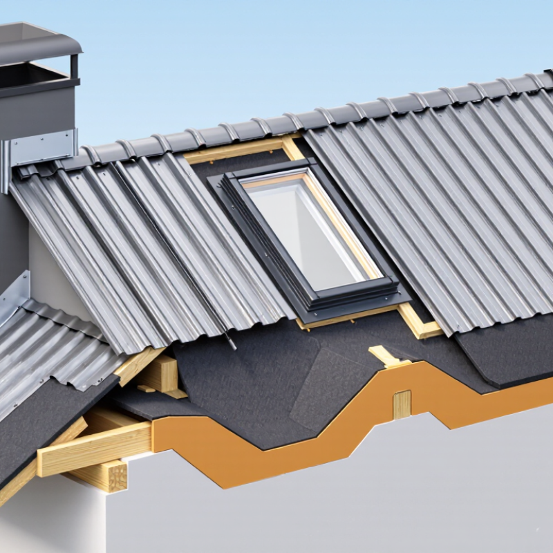
Installing metal roof flashing requires more than folding thin metal around an opening. It must guide water away from seams, joints, and exposed edges. Before cutting, inspect the roof pitch, panel profile, and penetration size. Dry-fit each piece around the vent or pipe. Leave room for thermal movement, but avoid a loose fit. A clean work surface matters.
Around roof vents, slide the upslope flashing beneath the metal panels whenever the roof design allows. Place the downslope section over the panels, creating a shingle-like drainage path. Seal fasteners with compatible washers and use a sealant rated for exterior metal roofing. Do not depend on sealant alone. Water often finds the smallest gap. At side walls, install step flashing in short overlapping sections, then cover the upper edge with counterflashing set into the wall joint. Keep laps facing downhill. Wind-driven rain tests every weak detail.
Wall intersections need careful alignment. Mark cuts slowly, because one rushed notch can distort the panel. Around pipes, use a flexible boot or formed collar sized to the pipe, then secure its top edge while allowing controlled movement below. Check the collar after tightening; over-compression can split the seal.
I have found that a small uneven bend may look harmless, yet it can hold water. Recheck corners from ground level and the roof surface. Some installations need adjustment after the first rain. That's not failure. It is useful evidence.
Sealing, Fastening, and Inspecting the Finished Metal Flashing
How to Install Metal Roof Flashing?
Sealing and fastening determine whether metal roof flashing remains watertight. Clean the roof surface before installation. Remove dust, oil, loose rust, and old sealant. Dry the joint completely. Apply a continuous bead of compatible roofing sealant beneath the flashing edge. Avoid gaps around corners and laps. At overlaps, extend the sealant beyond the expected water path. Water finds small weaknesses.
Fasten the flashing with corrosion-resistant screws and sealing washers. Place screws at the recommended spacing, keeping them perpendicular to the panel. Overtightening can crush the washer and damage the metal. Under-tightening may leave a visible leak path. Leave enough room for normal thermal movement where the design requires it. In practice, I often recheck screw pressure by hand because visual inspection can be misleading. That small step prevents careless errors.
Tips
Inspect every lap, corner, and penetration from several angles. Look for lifted edges, cracked sealant, exposed holes, or distorted washers. Lightly test suspicious joints with controlled water flow, never with a high-pressure nozzle. Check the underside for damp insulation or dark timber marks. Do not rely only on a dry surface; hidden moisture may appear later. Take clear photographs during inspection, especially around chimneys, roof valleys, and wall transitions. If a detail feels forced, stop and review it against the roof design and applicable building requirements. A neat appearance is not proof of a reliable seal.
Related Posts
-
2026 Best Metal Flashing Techniques for Your Construction Projects?
-
How to Properly Install Metal Roof Flashing: A Step-by-Step Guide
-
Essential Guide to Metal Roof Flashing Techniques and Benefits
-
Top 10 Metal Roof Flashing Types Which Is Best?
-

2026 Top Wall Panel Types What Should Global Buyers Choose?
-

2026 Top Roof Panels for Global Buyers to Consider?