




What Are the Top Types of Motor Threaded Shafts?
Electric motors power pumps, conveyors, machine tools, and countless other systems. The International Energy Agency’s 2011 report, Energy-Efficiency Policy Opportunities for Electric Motor-Driven Systems, estimated that these systems use roughly 45% of global electricity. That figure covers complete motor-driven systems, not threaded shafts alone. Still, it shows why dependable motion components matter.
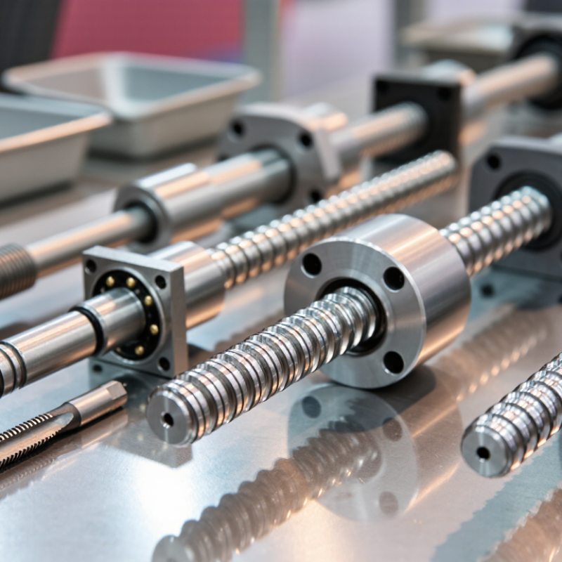
A Motor Threaded Shaft converts rotation into controlled linear movement or provides an adjustable connection. Its thread profile, material, finish, and load rating affect fit, wear, noise, and service life. Common designs include lead screws with trapezoidal or Acme threads, ball screws for lower-friction movement, and rolled or ground threads made for different accuracy and production needs. Stainless steel may suit wet environments; hardened steel may better withstand demanding loads. Small details matter.
No single type is best for every motor. A compact actuator moving a light gate has different needs from a machine axis cycling under load. Selection should account for speed, travel, alignment, lubrication, duty cycle, and expected maintenance—not just nominal strength. A higher-precision shaft can also add cost without solving a poor support or alignment problem. That is easy to overlook. This guide compares the leading types of motor threaded shafts, explains where each fits, and highlights the trade-offs engineers should check before specifying one.
What Is a Motor Threaded Shaft and How Does It Work?
A motor threaded shaft is a rotating shaft with helical grooves cut into part or all of its length. The motor supplies rotation; the threads determine how that movement is used. Some shafts have only a short threaded end, which secures a pulley, gear, or coupling with a nut. Others work with a matching threaded nut to move a load in a straight line. These designs look similar at a glance, but they serve different jobs.
In a linear-motion setup, the motor turns the shaft while a nut travels along its threads. The nut may carry a small platform, valve, or positioning mechanism. Thread pitch matters: a finer pitch usually moves the nut less per revolution and can allow more precise positioning, while a coarser pitch travels farther. Real performance also depends on load, speed, lubrication, and alignment. A shaft that bends slightly can make motion uneven or accelerate wear.
That distinction is easy to miss. A threaded shaft does not automatically act as a lead screw; the nut, support bearings, and mounting arrangement must suit that purpose. For a simple retaining thread, check the fastener size and rotation direction. For linear motion, check pitch, travel, and the force required. Measure carefully, too—small thread differences can prevent a nut from fitting or moving smoothly.
Which Thread Forms Are Used in Motor Shafts?
Which thread forms are used in motor shafts depends on whether the thread secures a part or transfers motion. Most motor shaft ends use a V-shaped metric thread for retaining a pulley, fan, or coupling. ISO 261 lists preferred metric thread dimensions; for example, an M8 coarse thread has a 1.25 mm pitch. That small spacing helps match nuts and retainers, but it does not make the thread a precision drive mechanism.
For linear motion, trapezoidal threads are more suitable. ISO 2901 specifies profiles for metric trapezoidal threads, while ASME B1.5 covers Acme threads. Their broader flanks can carry axial loads and tolerate practical workshop conditions. Square threads can offer high efficiency, but they are less convenient to manufacture and inspect. In real motor assemblies, the shaft drawing matters: a thread may be only a short end feature, not the surface transmitting torque. A common oversight.
Tips: Check the thread callout, pitch, engagement length, and rotation direction before selecting a nut or coupling. A caliper alone cannot reliably identify pitch; use a thread gauge and verify the drawing. Standards define geometry, but actual load capacity still depends on material, fit, and installation.
What Are the Main Types of Motor Threaded Shafts?
Motor threaded shafts are commonly classified by thread location, direction, and profile. An externally threaded end is the familiar type: a nut or coupling screws onto the shaft, often securing a pulley or fan. Internally threaded ends use a tapped hole instead, allowing a bolt to fasten a hub or accessory. Some shafts are threaded at both ends, useful when two components must be mounted along one axis. Small detail, big consequence: a mismatched thread can loosen under vibration.
Direction matters too. Right-hand threads tighten clockwise; left-hand threads are used where rotation could loosen a conventional nut. Thread profiles include metric or unified V-threads for fastening, and trapezoidal or ACME forms for motion transfer. A lead screw is not simply a threaded motor shaft: it is designed to convert rotation into linear travel, often with a matching nut and guide. Check pitch, diameter, handedness, and usable thread length before specifying a replacement.
The U.S. Department of Energy’s motor systems sourcebook estimates that motor-driven systems account for about 68% of electricity use in U.S. manufacturing. That figure is not a shaft specification, but it highlights why correct component selection matters across many applications. For example, a fan motor may need a short threaded end for a retaining nut, while a positioning actuator needs a lead screw suited to its load and travel. The distinction is easy to miss. Real assemblies can also vary from drawings, so measure the shaft directly.
How Do Shaft Materials and Finishes Affect Performance?
What Are the Top Types of Motor Threaded Shafts?
Motor threaded shafts commonly use straight, stepped, or shouldered designs. Their thread may secure a pulley, gear, or coupling. The right shape depends on the motor’s load and how components attach. Fit matters. Even a small mismatch can cause vibration or uneven wear.
How Do Shaft Materials and Finishes Affect Performance?
Material and finish influence strength, corrosion resistance, and friction. Carbon steel is strong and economical, but exposed surfaces may rust in damp settings. Stainless steel resists corrosion, though its strength and machinability vary by grade. Alloy steel can handle higher loads when properly specified and heat-treated.
A ground bearing surface can reduce friction where the shaft rotates in a support. Plating may help resist corrosion, but it also changes dimensions. That detail is easy to overlook. A smoother finish is not automatically better if it reduces lubricant retention or pushes a part outside its fit tolerance.
Tips: Check the shaft drawing for thread size, material grade, hardness, and surface finish. Measure the bearing journal, not just the threaded section. Match coatings to clearances, and inspect for burrs or damaged threads before assembly. A specification can still miss real operating conditions.
How Do You Choose a Motor Threaded Shaft for an Application?
A motor threaded shaft should be selected from the motion it must deliver, not just its diameter. Record axial load, travel distance, speed, duty cycle, and available space. A short shaft pushing a heavy carriage has different needs from a fast positioning axis. Fit matters. Check whether the design uses a ball screw for smoother, efficient motion or a trapezoidal lead screw for simpler, often self-locking movement. Neither is automatically right; efficiency, backlash, noise, and maintenance all affect the choice.
Check the shaft’s critical speed and buckling limit at the actual unsupported length. Also confirm thread accuracy, bearing alignment, and whether dust, moisture, or temperature changes could affect operation.
ISO 3408 covers ball-screw dimensions, accuracy, and acceptance testing, giving engineers a consistent basis for specification.
The U.S. Department of Energy’s 2014 Improving Motor and Drive System Performance sourcebook estimates that motor-driven systems use about 68% of U.S. industrial electricity. That figure is a reminder to consider the full motion system, including motor load and operating hours, rather than oversizing the shaft “just in case.”
Small details matter. A mismatch between shaft lead and motor speed can cause missed positioning targets, even when the shaft itself appears robust. Verify the selection against the real load profile; estimates can be imperfect.


