How to Choose an ESS Connector in 2026?

As global battery deployment accelerates, choosing an Ess Connector in 2026 requires more than matching a plug to a cable. The International Energy Agency’s Batteries and Secure Energy Transitions report states that global energy storage capacity must expand sixfold by 2030, reaching 1,500 GW. This growth will place greater pressure on safety, serviceability, and supply-chain reliability.

The connector sits between stored energy and human operators. A poor selection can create heat, voltage drop, difficult maintenance, or unsafe separation during service. The tempting answer is simple: choose the largest connector. That answer is incomplete. Real projects need a verified balance between continuous current, peak current, DC voltage, ambient temperature, vibration, ingress protection, and mating cycles. NREL research on battery energy storage emphasizes system-level safety, thermal behavior, and reliable monitoring. These concerns extend directly to connection points inside cabinets, racks, and outdoor enclosures.

A practical evaluation should examine UL 1973, UL 9540, IEC 62933, and applicable installation requirements. Certification alone does not prove suitability for every battery architecture. Engineers should also review derating curves, creepage distances, touch protection, flame performance, contact resistance, and field-replacement procedures. A connector that performs well in a clean factory may struggle beside dust, condensation, and repeated thermal cycling. Small details matter. For example, an installer should be able to confirm locking engagement without guessing.

This guide explains how to compare ESS Connector designs for 2026 projects. It also questions common assumptions, because connector specifications are sometimes copied without enough site evidence. Reliable decisions come from documented testing, qualified suppliers, and realistic installation experience.

How to Choose an ESS Connector in 2026?

ESS Connector Fundamentals and Their Role in Energy Storage Systems

An ESS connector is more than a plug between a battery rack and an inverter. It carries high current, maintains polarity, and helps keep stored energy under control. A sound design begins with rated voltage, continuous current, short-circuit exposure, and temperature rise. Small details matter. A connector rated for brief peak current may fail under constant load.

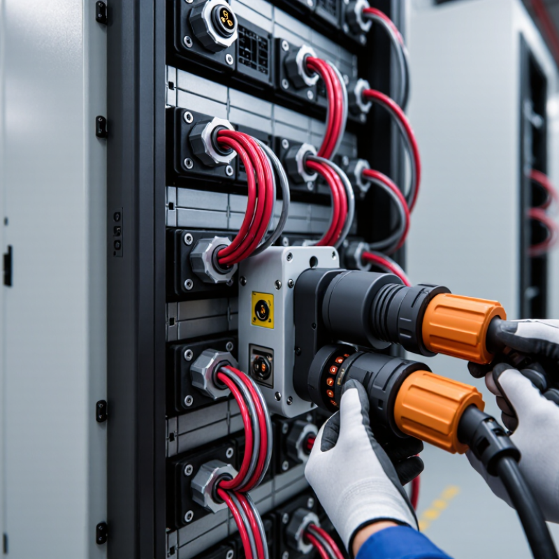
In field evaluations, I check contact resistance, locking force, cable flexibility, and protection against accidental touch. A secure connector should resist vibration without loosening. Its housing should tolerate dust, moisture, and the expected installation environment. Clear keying also prevents reversed connections during maintenance. For outdoor systems, sealing performance and ultraviolet resistance deserve close attention. For indoor cabinets, heat management may matter more than weather sealing. The best choice depends on the actual system, not a product label.

Testing should include repeated mating cycles, pull-force checks, insulation verification, and thermal imaging during operation. Inspect discolored contacts carefully; they may indicate rising resistance or poor crimp quality. Technical files should support relevant safety and performance requirements in the target market. Yet specifications can mislead when installation conditions are ignored. I have seen a connector pass a bench test but perform poorly after tight cable bends and repeated vibration. That is a useful warning. Select the connector with its cable, busbar, fuse, and enclosure as one working assembly. Reliability is built at the interface.

Define Voltage, Current, and Environmental Requirements

How to Choose an ESS Connector in 2026?

Define the voltage before comparing connector shapes. Record the battery’s nominal voltage, maximum charging voltage, and possible transient peaks. A connector rated only for normal voltage may fail during switching events. Check creepage and clearance distances, especially in compact enclosures. These details reduce arcing risks and support dependable insulation performance.

Current requirements need equal care. Measure continuous current, peak current, and expected overload duration. A 200-amp system may briefly demand much more during inverter startup. Select contacts with suitable thermal capacity, then apply derating for enclosure temperature and cable grouping. Low contact resistance matters. Even small losses can create noticeable heat at high current.

I once reviewed a system where the cable size looked adequate, but loose contact pressure caused discoloration near the terminal.

Environmental conditions often decide service life. Define operating temperature, humidity, dust exposure, vibration, and possible condensation. Outdoor ESS equipment may also face salt mist or chemical vapors. Look for verified sealing performance and materials suited to the installation site. Laboratory ratings are useful, but field conditions are less tidy. A connector can pass a clean test and still fail after repeated vibration. Review test methods, mating cycles, torque values, and maintenance access. Do not rely on a single rating. The right choice combines electrical margins, mechanical stability, and evidence from realistic testing.

Compare Connector Types, Materials, and Contact Designs

How to Choose an ESS Connector in 2026?

Choosing an ESS connector starts with the circuit, not appearance. High-current battery links need low-resistance power connectors with strong retention. Busbar connectors suit compact battery modules and reduce cable clutter. Cable connectors offer easier routing and field replacement. Board-to-board types work well for monitoring signals, but they are rarely suitable for main power paths. Leave room for maintenance.

Material selection affects heat, corrosion, and service life. Copper alloy contacts usually provide reliable conductivity and mechanical strength. Tin plating can control cost and support common power connections. Silver plating performs better under higher current and temperature conditions, but it requires careful compatibility checks. Stainless steel helps springs and shells resist corrosion, though it conducts poorly as a primary contact. Housing materials should resist heat, vibration, and flame spread. A small clearance mistake can become a serious design weakness.

Contact design deserves close testing. Pin-and-socket contacts provide familiar, stable mating. Blade contacts can carry high current in a shallow profile. Spring contacts maintain pressure during vibration, but their force may decline after repeated cycling. Wiping action removes light surface films during mating. Useful, but not magic. Measure temperature rise at maximum continuous current, not only during a short laboratory pulse. Check contact resistance, mating cycles, creepage distance, and locking force. I have seen connectors pass initial tests yet loosen after thermal cycling. That failure often comes from poor strain relief, not the contact metal.

How to Choose an ESS Connector in 2026? — Compare Connector Types, Materials, and Contact Designs

Comparison of commonly used connector approaches for battery energy-storage systems. Electrical ratings are typical engineering ranges rather than universal limits; final selection must be verified against the connector manufacturer's datasheet, system voltage, fault current, temperature, cable size, and applicable safety standards.

Selection Dimension High-Current Bolt-On Busbar Connection High-Current Plug-and-Socket Connector Touch-Safe Modular Power Connector Signal, Control, and Communication Connector Board-to-Busbar or Laminated-Busbar Connection
Typical ESS Location
  • Battery module terminals
  • Rack busbars and power distribution units
  • Permanent internal connections
  • Battery racks and cabinet interfaces
  • Service disconnects
  • Portable or replaceable battery assemblies
  • Modular battery packs
  • Rack-to-rack power links
  • Field-installable DC distribution
  • Battery-management systems
  • Temperature and voltage sensing
  • Contactor, interlock, and communication circuits
  • Battery modules mounted directly to a busbar
  • Compact power-electronics assemblies
  • Low-inductance internal current paths
Typical Current Capability 50–1,000 A
Depends on conductor cross-section, temperature rise, bolt preload, and busbar design.
100–600 A
Higher-current versions exist, but continuous current is strongly affected by cable size and cooling.
20–350 A
Suitable for modular power paths where touch protection and fast installation are priorities.
0.1–20 A
Power contacts may be rated higher, but signal contacts are normally selected for low-current circuits.
50–1,500 A
Current is governed mainly by busbar thickness, joint area, thermal path, and allowable temperature rise.
Common DC Voltage Range Up to 1,500 V DC
Insulation, creepage, clearance, and working-voltage requirements must be checked for the complete assembly.
Up to 1,500 V DC
Touch-safe shrouds, keyed housings, and an appropriate DC rating are essential.
Up to 1,500 V DC
Often used in high-voltage battery systems when finger protection and polarization are required.
Typically below 60 V DC
Higher-voltage auxiliary connectors require additional insulation and touch-protection measures.
Up to 1,500 V DC
Voltage capability depends on spacing, encapsulation, insulation system, and environmental conditions.
Contact Design
  • Flat copper or copper-alloy lug
  • Bolted clamped joint
  • Optional plated contact interface
  • Spring-finger, lamella, or multi-point socket contact
  • Positive locking mechanism
  • Optional auxiliary or pilot contacts
  • Stamped-and-formed or machined socket contact
  • Contact springs maintain normal force
  • Keyed and touch-safe mating interface
  • Stamped spring contacts or machined pins
  • Multiple contact sizes in one housing
  • Shielded pairs may be used for data circuits
  • Direct pressure contact or bolted interface
  • Stamped copper spring fingers may accommodate tolerance
  • Short current path and low loop inductance
Preferred Contact Materials
  • Electrolytic copper for high conductivity
  • Copper alloy where greater mechanical strength is needed
  • Tin or silver plating selected for the environment and current level
  • Copper alloy spring contact
  • Silver plating for high-current or high-temperature applications
  • Tin plating for many general-purpose copper interfaces
  • Copper alloy contact system
  • Tin plating for cost-effective power connections
  • Silver plating for demanding current and temperature conditions
  • Copper alloy contacts
  • Gold plating for low-level signals and repeated mating
  • Tin plating for many power and low-cost control circuits
  • High-conductivity copper or copper alloy
  • Tin, nickel, or silver surface finish depending on temperature and corrosion requirements
  • Surface flatness is critical for low resistance
Housing and Insulation Materials
  • Glass-filled thermoplastic insulating supports
  • Thermoset insulating parts in high-temperature designs
  • Metal hardware normally isolated from live conductors
  • Flame-retardant polyamide or other high-temperature thermoplastic
  • Elastomer seals for environmental protection
  • Optional shielding or strain-relief components
  • Flame-retardant, glass-filled polyamide or equivalent thermoplastic
  • Silicone or elastomer sealing elements
  • Color and keying used to prevent incorrect mating
  • Flame-retardant thermoplastic housing
  • Elastomer gaskets for sealed applications
  • Shielding shell may be nickel-plated copper alloy or conductive composite
  • Polyester, polyamide, or other electrical insulation system
  • Insulating films and molded barriers
  • Encapsulation may be used to improve vibration and contamination resistance
Serviceability and Mating Frequency
  • Best for permanent or infrequently serviced joints
  • Requires controlled torque and inspection
  • Not intended for frequent hot-plugging
  • Designed for repeated service access
  • Typical mechanical endurance: approximately 50–500 cycles, depending on design
  • Must not be disconnected under load unless specifically rated
  • Suitable for modular service and replacement
  • Typical mechanical endurance: approximately 50–1,000 cycles
  • Interlock or pre-charge functions may be integrated
  • Designed for repeated low-current mating
  • Typical mechanical endurance: approximately 50–5,000 cycles
  • Contact wiping action helps maintain signal reliability
  • Generally intended for assembly rather than routine service
  • Repeated removal can damage plating or reduce contact force
  • Fasteners and alignment features require controlled installation
Environmental Protection
  • Protection is provided by enclosure, covers, and barriers
  • Open joints require protection from dust, moisture, and accidental contact
  • Corrosion control is important in humid environments
  • Sealed versions commonly target IP65–IP69K when fully mated
  • Requires correct cable seal and backshell installation
  • Ingress rating may decrease when unmated
  • Commonly available with IP54–IP68 protection when mated
  • Touch-safe construction reduces accidental contact risk
  • Seal compression must be maintained during service
  • Unsealed board-level types may have no IP rating
  • Sealed cable types commonly provide IP65–IP68 when mated
  • Shield termination must be compatible with the enclosure strategy
  • Usually protected by the battery module or enclosure
  • Additional sealing or conformal protection may be needed
  • Contamination control is important at the contact interface
Main Advantages
  • Low contact resistance
  • High current capability
  • Compact and economical for permanent joints
  • Simple visual inspection
  • Fast field connection and disconnection
  • Good serviceability
  • Can combine power, pilot, and interlock circuits
  • Reduced wiring error with keying
  • Touch-safe and polarized
  • Modular installation
  • Supports high-voltage battery architectures
  • Can be integrated with pre-charge or interlock functions
  • Efficient monitoring and control integration
  • High contact density
  • Suitable for sensors and digital communication
  • Shielding options support electromagnetic compatibility
  • Very short and low-inductance current path
  • Compact packaging
  • Low electrical resistance when properly assembled
  • Suitable for high-power internal connections
Main Limitations
  • Requires accurate torque control
  • Limited service convenience
  • Loose hardware can create localized heating
  • Open live parts need robust barriers
  • Higher cost than simple bolted joints
  • Contact wear and contamination must be managed
  • Improper mating can cause overheating
  • Not automatically safe for energized disconnection
  • More complex housing and locking system
  • Higher insertion force at large contact sizes
  • Current derating may be required in tightly packed assemblies
  • Must verify creepage and clearance for system voltage
  • Not intended to carry main battery current
  • Signal integrity can be affected by noise and shielding errors
  • Small contacts are sensitive to damage and contamination
  • Pin assignment must be controlled carefully
  • Requires precise alignment and flatness
  • Usually not suitable for frequent field disconnection
  • Thermal expansion can affect contact pressure
  • Manufacturing tolerances must be tightly controlled
Best Fit for 2026 ESS Designs
  • High-current internal paths
  • Fixed battery-module connections
  • Applications prioritizing low cost and low resistance
  • Serviceable battery racks
  • Containerized storage systems
  • Installations requiring frequent module replacement
  • High-voltage modular racks
  • Systems requiring touch-safe maintenance
  • Field assembly with reduced wiring complexity
  • Battery-management and supervisory-control networks
  • Temperature, voltage, and current sensing
  • Contactor control and safety interlock circuits
  • High-density battery modules
  • Power-electronics assemblies with strict space limits
  • Designs requiring minimized parasitic inductance
Key Verification Items Before Approval
  • Continuous and peak current
  • Torque, joint resistance, and temperature rise
  • Short-circuit withstand capability
  • Creepage, clearance, and touch protection
  • Rated voltage and current under actual cable size
  • Contact resistance and temperature rise
  • Locking, CPA, and HVIL functions
  • Vibration, shock, and ingress performance
  • Finger-safe construction
  • Keying and polarization
  • Derating curve at the intended ambient temperature
  • Insertion force and service-cycle life
  • Signal bandwidth and contact resistance
  • EMC and shielding performance
  • Pin retention and miswiring prevention
  • Insulation resistance and environmental sealing
  • Busbar flatness and alignment tolerance
  • Contact pressure over temperature and vibration
  • Joint resistance and thermal distribution
  • Insulation barriers and manufacturing repeatability

Engineering note: Connector selection should be based on the complete operating profile, including continuous current, overload current, DC voltage, short-circuit level, ambient temperature, altitude, vibration, humidity, mating frequency, cable size, creepage, clearance, insulation resistance, touch protection, and required certification.

Evaluate Safety, Compatibility, Installation, and Maintenance

How to Choose an ESS Connector in 2026?

Choosing an ESS connector starts with safety, not appearance. Check voltage, current, temperature, and short-circuit ratings against the battery system. A connector should maintain stable contact during vibration, heat cycles, and emergency shutdowns. Confirm its insulation, touch protection, and locking design through credible test reports. A small mismatch can create heat at the contact point.

Compatibility requires more than matching plug shapes. Review conductor size, polarity, mating cycles, sealing level, and communication requirements. The connector must fit the battery enclosure and cable bend radius without stress. Use manufacturer datasheets and independent certification records. I have seen installations fail because the cable was technically compatible but physically too stiff.

Installation quality affects long-term reliability. Follow the specified stripping length and crimp force. Use calibrated tools, then inspect the crimp for gaps or loose strands. Keep connectors clean and fully seated. Maintenance teams should check discoloration, looseness, corrosion, and unusual temperature increases during scheduled inspections. Do not ignore minor heat marks. They may signal rising resistance.

Tips: Photograph each connection before closing the enclosure. Record torque values and inspection dates. Leave enough service space for testing. A rushed installation may pass today but complicate tomorrow’s repair. Recheck assumptions after the first operating season. Some field conditions will surprise you.

Select the Best ESS Connector for Long-Term System Performance

Choosing an ESS connector in 2026 requires more than matching voltage and current ratings. Long-term system performance depends on stable contact resistance, thermal control, and mechanical durability. A connector may pass a laboratory test yet weaken after years of vibration, dust, humidity, and repeated temperature changes. Check its operating temperature range, insulation quality, ingress protection, and resistance to corrosion. Confirm that the cable size fits securely without excessive bending.

From field experience, installation quality often decides connector life. A properly rated connector can still fail when crimping is uneven or contact surfaces are contaminated. Look for clear assembly instructions, verified torque values, and reliable locking mechanisms. I would not judge a connector by its appearance alone. Some compact designs save space but leave little room for inspection or maintenance. That trade-off deserves careful thought.

Tips: Compare the connector’s ratings with real operating conditions, not only nominal system values. Review test data for thermal cycling, vibration, salt mist, and mechanical endurance. Inspect sample assemblies before approving large quantities. Pull-test crimped terminals and record the results. Leave practical service access around each connection. It is easy to overlook this detail during design. Also, plan for future replacement, because an ESS should remain maintainable after installation, not merely functional on its first day.

How to Choose an ESS Connector in 2026?

Reference comparison of commonly specified DC connector performance levels for low-, medium-, and high-voltage battery energy storage systems.

Higher-voltage ESS designs generally require connectors with increased voltage withstand capability, while continuous-current selection must account for conductor size, ambient temperature, enclosure ventilation, and thermal derating. Confirm the final connector against the complete system voltage, current, environmental, touch-protection, and service-life requirements.